
designing a rainwater harvesting system with tank that is underground with filter system and irrigation controller and all the reticulation of piping and using 10 pop up sprinklers each at 30psi and 100L/hr flow rate 5fps

Designing a comprehensive rainwater harvesting system with underground tank, filtration, irrigation controller, and piping reticulation involves multiple components and calculations. Here's an outline and detailed guide for your system:
A rainwater harvesting system that feeds an irrigation network with 10 pop-up sprinklers requires careful coordination of collection, storage, filtration, and pumping. The design includes:
- A filtration system with multiple stages to treat the water for irrigation.
- An underground storage tank for consistent water supply.
- A pump and irrigation controller to automate the system.
- A pipe network sized to maintain the required pressure and flow for the sprinklers.
Step 1: System calculations
Irrigation demand
- Total Flow Rate: 10 sprinklers * 100 L/hr/sprinkler = 1,000 L/hr.
- Convert to L/min: 1,000 L/hr / 60 min = 16.7 L/min.
- Convert to GPM (for pipe sizing): 16.7 L/min * 0.2642 gal/L = 4.4 GPM.
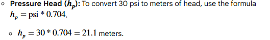
- Target Pressure: 30 psi (given).
- Required Flow: 1,000 L/hr (16.7 L/min).
- Total Dynamic Head (TDH): This is the total resistance the pump must overcome. It is the sum of pressure head, elevation head, and friction loss.
- Elevation Head (): This is the vertical distance from the pump to the highest sprinkler. The sprinkler operates on the surface, while the pump is likely just above or in the underground tank. Assuming a 2-meter rise from the pump outlet to the sprinkler surface, the elevation head is 2 meters.

- Friction Loss (): This pressure loss occurs from water moving through pipes, fittings, and filters. For a velocity of 5 fps, you can use online calculators or friction loss tables to estimate the loss for your pipe diameter and length.

- Elevation Head (
- Selecting a Pump: Use the calculated TDH and required flow rate (16.7 L/min) to choose a pump. A submersible pump placed inside the underground tank is suitable for this application.
- Total Flow: 4.4 GPM.(16.7 L/min )
- Velocity: The specified velocity of 5 fps (1.5 m/s) is the recommended maximum to prevent excessive wear and inefficiency.
- Pipe Diameter Selection: To stay below the 5 fps limit, a 1-inch pipe is sufficient for a total flow of 4.4 GPM(16.7 L/min ), as it typically handles up to 15 GPM without significant friction loss.
- Zone the Sprinklers: Instead of running all 10 sprinklers on a single zone, which could cause pressure loss, group them into multiple zones (e.g., two zones of five sprinklers each). This allows for more even water distribution.
Step 2: System components
- Catchment Area: The roof serves as the collection surface. The size of the roof and local rainfall data will determine the potential water yield.
- Gutters and Downspouts: These channels direct water from the roof to the filtration system. Ensure the downspouts are sized appropriately.
- Leaf and Debris Filters: Place filters at the top of each downspout to prevent large debris from entering the system.
- First-Flush Diverter: The initial, most polluted runoff should be diverted away from the tank. A first-flush diverter ensures that the cleaner water is stored.
- Multi-Stage Pre-tank Filter: Install a filter system before the water enters the underground tank. This typically includes a coarse filter to remove larger debris and a finer filter to reduce sediment.
- In-tank Filter: A calming inlet prevents incoming water from disturbing sediment at the bottom of the tank. A floating suction filter draws the cleanest water from the top of the tank to avoid drawing sediment
- Type: Use a durable, reinforced underground tank made of concrete, polyethylene, or fiberglass. The tank should have a lockable, child-safe lid.
- Installation:
- Excavate the area and create a stable, level base of compacted gravel or concrete.
- Use a non-woven geotextile liner to protect the tank from rough backfill material.
- Lower the tank and connect all inlet, overflow, and outlet pipes.
- Backfill with gravel and simultaneously fill the tank with water to equalize the pressure and prevent collapse.
- Overflow: Install an overflow pipe that directs excess water to a soakaway or storm drain to prevent flooding.
- Submersible Pump: This is an energy-efficient option for pulling water from the underground tank. Select a model that matches your flow and pressure requirements.
- Pressure Tank: A pressure tank can prolong the life of the pump by reducing start-stop cycles.
- Irrigation Controller: An electronic irrigation controller allows you to set automated watering schedules for different zones.
- Valve Manifold: Place solenoid valves in a sealable, underground valve box. This centralizes the control of each irrigation zone, with each valve wired to the controller.
Reticulation and sprinklers
- Mainline Piping: Use Schedule 40 PVC or Class 200 PVC for the main lines that supply water to the valve manifolds.
- Lateral Piping: Use smaller diameter polyethylene (PE) pipe for the lateral lines that run from the valve manifolds to the sprinkler heads.
- Pop-up Sprinklers: Space the 10 sprinklers head-to-head for even coverage, ensuring the spray pattern of one reaches the next.
- Trenches: Dig trenches deep enough to ensure the retracted sprinklers are flush with the ground.
- Fittings: Use appropriate threaded and barbed fittings for all connections. Dip PE pipes in hot water to soften them for easy installation onto barbed fittings.
- Pressure Regulation: If the water pressure is too high, install an inline pressure reducer to protect the system.
- Local Regulations: Check with your local water authority for any necessary permits for underground water storage and harvesting systems.
- Annual Maintenance:
- Inspect and clean the leaf screens, first-flush diverter, and pre-tank filter.
- Check for leaks in pipes and fittings.
- Inspect pump and check the tank's water quality.
- Clean any dirt or debris that has built up around the sprinkler heads.